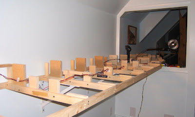
My next step is to complete the power district wiring, and then to run the buses for the 3 auto reverse (AR) sections (you can see some of the yellow/blue AR wire pairs in the photo). Once done with that it will be time for the 1/2" plywood subroadbed -- I got another 4x8 sheet at Home Depot today for the purpose. (Lumber prices, after the last few years of outpacing inflation, have suddenly dropped like a rock. This is logical given that construction demand has all but disappeared, but this means I may want to rethink some of my plans to take advantage of the lower prices.)
I won't go into the detailed process for setting up the piers, but for anyone considering tackling a similar project there are a few things to be aware of before starting:
- Model Railroad CAD software can plan the locations of our track down to 1/16th of an inch in 3 dimensions, but expect to make many adjustments tranferring those virtual locations to reality. This is especially true if building along a wall, as I am here, as walls are very rarely straight and, in the case of my garage loft, can skew off center by an inch or more from one end to the other. So you can't rely on the wall as a horizontal reference point. Ditto for the floor as a vertical reference point -- floors are rarely level to the fine accuracy that our CAD software assumes they are. So, when setting up your horizontal measurements use a few local reference points then draw lines to make sure that the track locations you've plotted from different locations line up nicely before doing any actual building. I pencil in the track locations on the girders themselves. Similarly for vertical measurements, always link up to the new part of the layout to the existing layout and adjust levels and grades as needed to compensate.
- Levels are your friend. I use 3 levels in the measuring process: A 6+ ft level for assuring piers are consistent (either level or at grade) over a long distance, and also for determining required grades over long distances; a 2 ft level for near distance pier-to-pier alignments; and a 9 inch level for checking that piers are level side-to-side.
- Fix mistakes as you make them. Sounds simple, but when you are in the middle of a long process like this (62 individual wood pieces, each cut to size and painstakingly put into exact place, at about 5-6 per hour) it's tempting to ignore a mistake "for now" and press on in hopes of reaching completion sooner. Well, at least it is for me. I really have to force myself to measure fully everything after each new piece is in place and redo it if necessary -- but this practice is time-saving in the long run. Fortunately, after a while of doing repetitive work you get so that your mistakes are rare.
One other point to note has to do with vertical curves. You'll see a reasonable amount of discussion on this topic on layout design forums, but most of the detailed write-ups I've seen use HO scale, and thus often need adaptation for N scale.
For this implementation I'm letting the 1/2" plywood subroadbed provide the smooth spiral transition from level to grade and back again. Doing this does require planning the vertical curve such that the 1'-apart piers will provide the support at the right places in the transition and that the joints in the plywood subroadbed occur only at places where the grade is constant -- since we need continuous plywood throughout the transition to make sure it is smooth.
In the past week this has been my main project. However, I've also done a little bit of work on the planning of the switch automation. More on this in a couple weeks after all the staging track is in place.
No comments:
Post a Comment