Showing posts with label outdoor construction. Show all posts

Monday, November 8, 2010

More pathways and stairs

Work outdoors has been slow. On the plus side weather has been unusually warm. On the minus side, I've been able to make progress only on weekends. On Saturday, October 23rd, I put in some more stone steps and also installed another conduit for future electrical lines, as shown in this picture:


The conduit is 30' long. Work continued outside, including several trips to the landscape materials yard for sand, stones, and the "red breeze" clay/gravel mixture. By Sunday morning, November 7th much progress had been made on the paths. On Saturday I hauled 1.4 tons of red breeze and 1.4 tons of sand, and moved all of that via many, many wheelbarrow loads. This picture shows the red breeze in place:


This next picture shows the sand in place in what will someday be the patio in front of the main porch. You can also see that the stone steps are set and almost ready (I will be adding mortar to them, probably next spring, to add stability:


I'm still not sure exactly what type of masonry I'll use for that patio. Meanwhile, I've started placing the "Colorado rose" flagstones in place on the patio by the pond.

Between the stone steps and the porch will be a short foot bridge that will go over part of the train line. This area has been dug out extensively this past summer to reduce the grade needed for the train line, but now I need to finish the stone steps and design the footbridge so that it is easily removable -- as occasionally I'll need to perform maintenance on the tracks underneath. This picture shows that area as it is now:


Stones on the left, a mini-deck on the right, and some landscape timbers and spikes in the middle where the tracks will ultimately be located. I'm going to use the landscape timbers to frame the short line segment where the tracks will go (this section will be double tracked as it will include a siding) and those timbers will also serve as the base for the bridge. I've bought the materials and cut the landscape timbers to size -- if the weather cooperates I might be able to get them all in place before it gets too cold.

Finally, on Sunday I spent the day prepping for winter, performing numerous necessary pre-winter tasks, which are - alas - a prerequisite of this area. Winterization work has been going on for a few weeks now -- I moved the pond goldfish to an inside tank about 2 weeks ago. Today I did one other winter thing, this time related to the garden railway. In a few spots the planned rail line markings have worn thin, or they were marked by metal tent stakes that were falling over. I replaced all track markings with wooden stakes that will survive the winter, so that I won't need to remeasure their locations in the spring.

At this point the best I can hope for is to complete the footbridge footings before winter gets too intense. From this point forward I expect most work will be focused on the N scale layout.

Sunday, October 10, 2010

Towards Stairways

The last post covered work through the morning of September 5th. With the digging done and dirt tamped down the next steps were to put the edgings in place and the fabric cloth down to cover the dirt pathways. These next two pictures taken the morning of September 18th show that work has been complete and, in addition, the first ton of sand has been added on the ground of the pond patio:


That picture is from the driveway side of the pond patio. The edge of the pond is to the right, reflecting the morning light. The patio is straight ahead, with green edging on the sides, and a bit of white fabric cloth is showing underneath the sand. The construction of this patio will be standard flagstone-on-sand.

At the bottom of that photo you can see the newly-added dirt is sloped away from the patio edging. Erosion is a definite concern. I made sure that the slope is no steeper than 1-in-2 (about 33%) and tamped it extensively. However, I will be adding in embedded stakes and something to cover this during the winter to prevent erosion. You can also see a black-painted stake in front of the edging - the track will be running along this side of the patio and then along the driveway side of the pond.

One thing you can see in this photo and the next are a lot pine needles on the ground -- a reality of this time of year. This next picture is from the front of the house and shows the edged pathway extending from the pond patio:


The next three pictures were taken yesterday. This first one was taken from the pond patio looking south toward the front patio:


You can see flagstones on the ground. Actually we won't have any flagstones on the pathway -- that will be "red breeze" like the bridge approaches -- but these are staged for use on the pond patio. I started to place those then I realized it would be better to have the rest of the sand first.

This next one is from the south side of the front patio looking north towards the pond:


The rock walls and the fabric cloth for the pond patio are complete in this photo. You can also see the first two steps on the stairway to the front porch. I decided to use something that looked "natural" but was somewhat varied from what we have elsewhere in the garden. These are "siloam" rock steps -- basically slabs of siloam rock that have a flat surface to be used as stones. I am trying for 7" risers and 11" steps, but of course it is approximate. A ton of this type of rock is about $100, which is enough for 3 steps. Getting these into position involves a lot of trial and error, and the time involved depends on your experience and what compromises you'll accept. I focused more on safety than on looks, but I think it is okay.

Here is the last photo for this post, which is just in front of the front stairs:


That photo was taken late yesterday afternoon. After much consideration of possible building materials for the stairway from the front porch I decided to start with a deck extension, shown in this photo, and then transition to stone steps.

Last weekend I put in the concrete piers for this structure -- basically just pre-molded piers, placed in dug holes and leveled, then surrounded by poured concrete (one 60 pound bag per two piers). This weekend I built the substructure using pressure-treated fir and strong tie connectors.

There is still a little work to be done at the transition areas on the porch side and the left side, and I worked on some of that today. I actually rebuilt the bottom two porch stairs. It turns out the second porch stair was misconstructed and was shorter than the other two, which made the stairway somewhat awkward to use. I took the stairs off and added wood extenders to make the stair normal width. This also will serve to extend the bottom stair over this new deck, so the transition will look natural.

My next step is to finish off this structure, then work on finishing the stairs connecting the front patio to the front porch. Will it be done by Hallowe'en?

More outdoor paths

Following up on the last post, construction began with the patio area on the south side of the pond. I wanted to have a gathering spot near the pond and that place made sense due to proximity to the footbridge staircase and also being a logical connecting point for a stairway to the driveway and a path to the front of the house. The patio will be made of "Colorado Rose" flagstone, which not only fits nicely but is also mostly free as a neighbor gave me their leftover flagstones.

The first challenge was that the patio area needed a lot of dirt fill to raise it up. Partly this was because I wanted the patio higher than the existing ground anyway, but also in part because I want to raise the sides of the pond early next year, as noted in the last post. I created walls to hold the dirt in using the old pieces of ground-contact 4x6 beams, held in place with 12" rebar pounded into the ground. Now, where to get dirt to use as fill?

Well, part of the rest of the plan was to build a flat patio in front of the house, roughly 8x10, and to have stairs down to the patio from the front porch. The front patio would connected to the pond patio via a 3.5' wide path. Since the ground in front of the house was fairly steeply sloped I would need to dig quite a bit to create a flat spot for the front patio and the pathway. So, I started digging the dirt for the front patio and using it to fill in the pond patio.

By September 5th progress had been made. This first picture shows the pond patio area, taken from the footbridge:


Compared to the pictures of the same area in the last post much has changed. You can see the dirt fill-in, varying in depth from 6" to over 2' at the far end of the picture near the driveway. The dirt has been tamped down several times, watering between each iteration, to make it solid. You can see the start of building green metal edgings -- these edgers are 4" tall and will add that much height to the patio. (They were in place by the end of the day on the 5th.)

If you look closely you'll also see evidence of an electrical conduit Near the top of the photo is a black-topped skimmer box for the pond, which houses the pump. Just to the right of that is a grey pipe, curved, that is sticking out of the ground. I used 1/5" schedule 80 pipe and ran 20' of it under the patio. This will all me to later add an electrical box at that location, both for powering the pond pump (and future lights) but also for general outdoor electrical outlets. The pipe opening is covered and will be this winter to keep it clean and dry inside.

Finally, note the colored stakes gathered on the ground at the bottom of the photo. As planned elements are built the stakes are removed and sometimes reused.

This next photo, taken at the same time, shows the view from the pond patio area looking south:


This shows that the front patio has been dug out as has the pathway between the two patios. The ground near the bottom of the photo has been tamped down as that is where the dirt fill began. The most prominent feature is the new rock wall along the new pathway. We inherited quite a few walls in the front yard built of these types of rocks, and the same rocks were used as edging in various places. I had to remove quite a few of the rock edgings during construction of the pond and stream, and even more during construction of the foot bridge where the bridge ends at a rock wall. As part of this project I re-stacked the rock wall near the footbridge and used the leftover rocks for this wall.

The overall effect from a distance works well, giving the front yard a tiered effect, but flowing rather than rigid, uniform tiers. Plus the added advantage of reusing materials, thus saving money.

At this point the cost of the patios had been remarkably low. The conduit and rebar together were under $75 and everything else was reused. For the next section I'd need to buy more edging, as the leftover edging from the bridge project ran out, adding about $100, plus a couple of tons of sand at under $15 each (the savings of picking up sand yourself rather than buying the bagged stuff or having it delivered is stunning). Costs would go up just a bit with the stairs, but I'll cover that and the last month's work of construction in the next post.

Saturday, October 9, 2010

Outdoor paths

So my last post was 2 1/2 months ago. Just like last summer, I have again failed to keep the blog up-to-date while garden railway work was in progress.

So, it's safe to say that this summer wasn't as productive as last summer. OTOH, last fall at this time I had broken my rib and had to stop work early, whereas this year I should have at least 3 more productive weeks ahead of me, helped by the warm October we are having.

My last words from the last post on June 28 were: "If things go well I hope to have the roadbed for the main line roughly in place by the end of the upcoming holiday weekend." If only. Two things really impacted progress this summer. First, I was talked into volunteering for a local community organization, right about the time of that last post, and it has taken a ton of time. Second, I had a serious design problem to solve regarding track locations and, as has happened before, this caused me to stop progress until I found a satisfactory solution.

What I eventually figured out was that I needed to plot out in detail the locations of track, garden pathways, and underground electrical conduit in advance before starting any actual work. Otherwise if I started any one of those three without determining the other two in advance I could cause myself all sorts of trouble later on. Furthermore, the track locations in particular had to be very exact regarding grades.

The net is that I've now made a lot of progress on pathways and even electrical conduit. I also have a clear pathway for the main tracks, and even have bought a cool bridge for crossing the stream. But, alas, there will be no trains running in the garden this year. But we are now SO CLOSE -- next spring is a near certainty.

For reference, here is what the front garden, just south of the pond, looked like on June 13th. You see a lot of overgrown grass and two boxes that will be raised planters:


The month of July was spent contemplating, measuring, and some digging. In August I had a local stump removal guy get rid of the stump near the top of the porch stairs that I mentioned in the last post was causing some problems. Finally, on the weekend of August 21-22, I started seriously plotting out the locations of the track (using black paint and stakes, very carefully setting out 12' radii, often in difficult-to-reach locations), followed by locations of walls (green), pathways (orange), and electrical conduit (blue). The next several pictures show how it all looked after locations were all diagramed. This first is in the area near the bottom of the bridge stairs, and shows the future patio bordered in orange, plus some blue (electrical) and black (train) lines:


This next photo shows the north side of the pond and the lines for three train tracks in black. The two on the right are the passenger station in Leadville, while the on the left is the track to the freight depot. Yes, this matches, schematically, the actual tracks in Leadville in 1882:


The next photos shows the ground on the west side of the footbridge, and if you look closely you can see the black-painted path for the single-track line that will go over the stream using that cool bridge I mentioned earlier. As with all other painted lines, I included stakes to mark the spot in case the rain washes away the paint:


Here is another view of the pond and the south side of the pond, this time taken from the footbridge. Emma, now 10 (we no longer have any children in the single digits!), is posing alongside the pond. You can see various black, green, blue, and orange lines. Note the green walls near the south side of the pond. After maintaining goldfish and pond plants for a summer in the pond one regret I have is that the pond is only 11" deep. Next year I intend to raise the sides of the pond by as much as 1' to allow for a deeper pond, one that supports a greater variety of fish and plants. The adjacent patio will thus be elevated to match the higher height of the pond:


This next picture shows the raised planters. You'll see the smaller planter has been moved to be higher and next to the larger one ... something that became obvious to me after planning everything out. You call also see lines of various colors all over and, if you look closely at the top of the photo, you can see how the ground near the porch is now several feet lower (due to digging), and there is evidence of the pile of leftover tailings from a stump:


This final photo shows the area in front of the porch. The orange lines show the boundaries of the stairs down from the porch, and a patio in the middle of the yard. The plan is to provide for several "gathering areas" for people to view the garden and the trains. It's not possible to really see in the photo, but in addition a two-track siding is planned (using black lines) that will go underneath the stairs from the porch. There also is a blue line for an electrical conduit underneath the stairs:


Now, here's the thing: the plan shown in these photos has happened, with only a few adjustments. No, the tracks aren't in place yet (dammit), but everything else is well on it's way, and that means that everything will be ready for the track in those exact locations early next year.

The next post will show progress on constructing the pathways, patios, and electrical conduits.

Monday, June 28, 2010

Dig It

Since the last post I've been doing a lot of digging. While planning out the track locations I realized that there is one 12' radius semi-circle that simply wasn't going to work because the grade would be over 15%. I started digging a little bit at the top to try to get the grade down to 4% (the maximum grade for the real Rio Grande narrow gauge, thus the maximum for this layout). But it turned out that "a little bit" wasn't going to be nearly enough -- I was going to have to reduce the differential between top and bottom by 3.5 feet. So, I've been steadily removing dirt from the top of the grade and moving it to the bottom.

Most of the really heavy work is now done. The main remaining problem is a large tree stump which used to be cut flat with the ground but now is two feet higher than the surrounding ground. I am out of town for my job right now, but when I get back I'll try removing the top of the stump with either a chain saw or a rental stump grinder. If things go well I hope to have the roadbed for the main line roughly in place by the end of the upcoming holiday weekend.

Saturday, June 12, 2010

Restarting the Water Feature and Finishing the Foot Path

In this post last year I talked about how I decided to use Aquascape's Microskimmer box to house the submergible pump. I also explained that the pond was too shallow (about 11" deep) to have the box sit in the pond itself, so I planned to create a permanent place for it just off the edge of the south side of the pond. Here is how the pond looked last summer shortly after the Microskimmer was in place:


So before restarting the water feature this year I wanted to get the MicroSkimmer box in place. The first step was to dig a hole for the skimmer box and level it at the right depth. My main concern was that digging close to the mortar walls of the water feature might weaken them or even make them break, so I starte about a foot away. This process was not hard, just a lot of trial and error to get the box at the right depth and level in both directions.

The MicroSkimmer box -- as with everything from Aquascape -- is pricey but very well designed. You need to attach the pond liner to it using their procedures. I couldn't readily find the 60 mil rubber I'd used for the main pond, but I found decent quality 40 mil material and folded it over -- effectively doubling the lining to 80 mil.

That was the easy part. The next part was to cut out enough of the mortar wall so that I could create a "mini-canyon" to connect the pond to the skimmer box. I found a concrete-cutting blade for the circular saw at Lowe's -- less than $3 per blade -- so took two and tried it out. I was cautious at first to not dig too deep for fear of cutting the underlying rubber lining, but as it turned out the concrete blade cuts concrete but didn't bother the rubber. Here is how it looked after that step:


You can see the cutout in the pond wall with the skimmer box in place behind it. There is a pile of rubber lining in front of the skimmer box because the lining has already been attached to the box so it has to sit there. The rubber lining on the pond had held up very well but was, of course, dirty and needed cleaning with mineral spirits -- which I had left over from the pond project last summer.

The next step was to dig the canyon to connect the skimmer box. Easy enough, but once done I realized the walls were too step to expect that they would stay in place by themselves, even with mortar on them. So I used left-over pressure-treated (p.t.) fir and two leftover metal stakes to give the walls some strength. This picture is after the first one was in place:


You can see the top of the p.t. fir along the "mini-canyon" wall that is not covered by the rubber lining. This block of p.t. fir doesn't need to cover the whole gap -- just enough of it to give the wall strength.

The next step was to cut the rubber linings (both the original and the new ones) so they overlapped nicely but not too much (about 3") and splice them. Cutting was easy with a box knife (new blade). But splicing liners is always a tricky business due to the potential of leaks. I started out intending to use some of the lining tape left over from the project last summer, but decided that wouldn't work the because the liners did not meet up nice and evenly -- in fact the two liners were coming at very different angles and there would have to be folds and compromises at the splice.

So, back to the home supply store. After looking at various adhesives intended for repairing holes in pools and on boats under the water line, I found something in the caulk section intended for showers with a 1 hour dry time. Reading the label they pointed out that if a product said "can clean up with water" then it isn't really water proof -- and they claimed their's was water proof. So I bought two caulk-gun-sized tubes to try it out.

I used one whole tube of the stuff between the original pool liner and the first of the new liners (remember I was doubling two 40 mil liners for this new section). It squished down nicely and did indeed appear promising for covering all gaps. I used a second whole tube between the first and the second of the new liners and again squished together nicely.

Now my theory was, and is, that if the caulking material is truly waterproof the splice will work because the weight of the mortar will hold the liners close together. I'll spoil the ending of the story and tell you right now that it did work - I tested the pond later for two days without running the waterfall and the water level stayed even the whole time, indicating no leak. Of course, we'd had similar results last summer with the splices using tape and some Polyseamseal, but this splice was more challenging.

Next step was to mix and stain some mortar, as we'd done last year, and add rocks for strength and decoration. Here is oldest daughter Paige adding the rocks (something she loves to do):


In the end, but before water was added, the skimmer box connection looked like this:


But would it work? Well we had to wait some time for everything to dry. In the meantime, there were other projects to do. One was to clean the water feature, washing out the internals of the skimmer box and the Biofalls box at the top of the water fall. We also needed to very carefully rake up pine needles and debris from the stream and pond. I'm happy to say that all four kids helped with some of this. Here is a picture of Laura helping rake the pond:


AND, it was long past time for me to put down the "red breeze" clay-rock mixture on the paths adjacent to the footbridge. Buying in bulk, and using my trailer, the whole purchase was only $11.30. Here is a picture of the north end of the bridge with the red clay-rock in place:


The work to do this was mindlessly simple (remember that weed-blocking fabric had been put in underneath the red-clay last year) but labor-intensive. Be sure to tamp-water-tamp a few times to get it solid. We've been very pleased with the appearance and utility of this. The kids are even now using the bridge for riding bikes over.

The next day was the great re-restarting of the water feature. Unlike last year this did not generate a huge amount of excitement. Kids checked in and looked, but didn't stay long as they'd seen this before. I was, however, very interested in if the skimmer box would work as expected. The answer: Yes, it did. This picture shows the skimmer box with the top open after I'd filled the pond just over the maximum point and the water was starting to run out the overlow pipe in the back:


Here is a view of the skimmer box within the context of the pond:


At that point the skimmer/pump had yet to remove all the water debris, but by later that day the water was as clear as glass.

Since then we have added fish and a few water plants. I've started planning the remaining footpaths and the exact location of the train tracks. I've also started installing raised planters. None of those things are visible in this photo, taken May 31st, of how the front yard looked on that day:


There still is a lot of work to do, but contrast this to last year on June 23rd:


So, we're happy with all that has been done in the last year, and looking forward to some real refinement and -- yes -- trains! this year.

    Thursday, June 10, 2010

    Footbridge Railings

    As you may recall, late last year I stopped work on the bridge due to an injured rib. At the time 
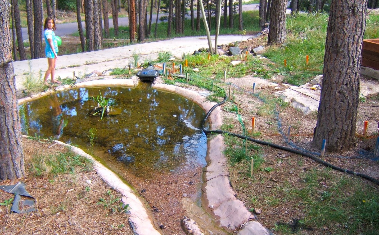
the footbridge looked like this:


    I started work on the railings after the snow thawed and I'd completed the normal spring forest maintenance. I finished the railings on May 23rd. These next four pictures show the bridge as it looked then. Note that at the time of these pictures I still had work to do on the paths leading up to the bridge, and had yet to complete the facial panels on the undersides of the north ramp. Also, the waterfall/stream/pond had not been restarted. All that would be completed by the 31st, which I'll cover in a future post.


    The rest of this post describes the construction methods used on the railings.

    Railing design is subject to local building codes. I am absolutely NOT an expert, so please do not rely on anything written here. I strongly advise you to do your own research for your situation. Having said that, typical building requirements include: 1) minimum railing height (36" in my case), 2) maximum width of any gap in the railing (4" for me locally, but this apparently varies), 3) railing design does not allow youngsters to "climb" the railing using horizontal footholds and the like, and 4) strength guidelines, which are pretty complex. In addition for stairs there is a requirement for a grippable hand railing, which I did not provide. There may be other requirements I missed -- please don't trust this write up for your situation!

    There is also a wide variety of choices in railing material. This includes pre-constructed railing parts made of special materials, which I rejected due to expense, and pre-constructed railing sections of cedar, which I rejected due to appearance and poor strength. I eventually decided to stick to redwood -- the same material as the surface of bridge. Posts would be 4x4s (nominal 3.5" x 3.5"), balusters (those thin vertical pieces of wood between the post) would be 2x2s (nominal 1 3/8" x 1 3/8"), and the top railing would be 2x4s (nominal 3.5" x 1.5"). The total cost for the railing materials was close to $1k.

    For construction all pieces were given a first coat of the same stain as the rest of the bridge BEFORE they were assembled. This serves two purposes. First, after assembly there are always places where the wood is joined that is exposed but can't be reached with staining tools. Pre-staining provides at least some protection for those areas. Second, it's easier to stain the parts of a railing in bunches on their own, as opposed to after they are all assembled.

    This custom footbridge has a lot of unique areas in terms of how it was constructed, so I started the railing at the simplest section -- the part of the bridge over the creek. This is very nearly level and each side of the bridge is comprised of a 2x8 length of redwood attached to two 2x8 pieces of pressure treated (p.t.) fir -- making attachment of the posts relatively easy. I started by cutting 4' lengths of 4x4 post in half, giving me 4' high posts. The posts were to be connected to the bridge sides with 2 screw-end lag bolts = 1/2" x 8" long, with a matching washer. The top of the posts were to be 35 3/4" from the bridge floor -- which meant that with the railing top the railing height would be about 37 1/4". (This just seemed a good height.)

    Note that this means part of the post extends below the bridge bottom. I considered trimming off the excess, but after looking at a number of pictures of railings in books decided I like this look. After doing the same thing with the balusters, this created a visual sense of the bridge gently transitioning from the bottom of the floor of the bridge to the scenic area underneath, rather than a sudden cutoff.

    The assembly method I settled on, after some trial and error, was as follows. I first measured the appropriate locations of the lag bolts on the post. The idea is that you want to keep the lag bolts as far from each other as possible, but also make sure both will be firmly anchored in the wood. I then drilled two holes using a 7/16" bit -- just slightly smaller than the 1/2" lag screw so that it could have some wood to "grab" to. Although I did everything possible to make the drill holes straight, some slight variation is possible, so I measured the location of the exit holes relative to the entry holes, vertically and horizontally. Typically the offset was no greater than 1/16", but on some occasions it could be as much as 3/16". Taking the offset into account, I marked the corresponding location of the top drill hole onto the side of the bridge. I then used a 3/8" drill bit to make a hole in the bridge side (keeping it as level and as perpendicular to the bridge side as possible). This meant that it would be a lot of work to get the 1/2" lag screw into place, but once into place it would hold tightly. (My drill was not strong enough to drive the lag screw -- I had to use a large manual rachet.)

    Holding the post closely in place, I screwed in the lag screw (with washer) through the post then partly through the hole in the bridge -- enough so that the post would stay in place unless I intentionally moved it. Then I verified that the post height was correct (if not, adjust). Then I used a vertical level to set the post straight and used a drill with a long bit, put through the second post hole, to mark the location of that hole on the side of the bridge. Be careful to center the marking as much as possible. Once marked, drill the second hole with a 3/8" bit, then add the second lag screw. As I got close to finishing the tightening of the lag screws I used the vertical level to see if the post was leaning inward or outward from the bridge, and if it was used shims (of p.t. fir or redwood) between the post and the bridge to make it as upright as possible.

    Ok, posts are now in place. The railing was comparatively very simple (assuming top of posts are level and in a straight line). Measure the length, cut, sand, stain, then attached to the tops of the posts using 3" deck screws -- 4 per post. Where the railing piece would share the top of the post with an adjacent railing, use 2 screws.

    Balusters were also 8' lengths which I cut in half -- so each baluster was a 4' length of 2X2. You want baluster spacing to be even and to have each one as vertical as possible. At the same time, because wood pieces tend to warp or bow you need to account for possible warpage and visually adjust the location of each to make sure it all "looks" decent and keeps within the code requirements for maximum spacing.

    My process for attaching balusters evolved, like everything else, through trial and error. The first step was to decide the exact placement of each one. While the code discusses the spacing between each baluster, many of the builders on web sites talk in terms of center-to-center spacing. I decided on a center-to-center standard of 4" -- which is closer than necessary. In part I did this because I wanted some extra room just in case two warped balusters were placed next to each other, creating an extra wide space. But even allowing for an extra "safety space" I think I could have gotten by with 4 7/8" or even 5" center-to-center spacing. But, 4" is the standard I started with, so I stuck with it.

    The next question is the spacing between the post and the first baluster on each side. Because posts are not evenly spaced on this bridge this is something that has to be figured out anew for each section. I eventually came up with this process. First measure the distance between the posts. For example, let's say 50". Then divide by 4" to get the remainder -- in this case 4x12 = 48 so the remainder is 2". Add 4" to the remainder (in this case summing to 6") and divide that number by two (result in this case: 3"). This number is will be the distance between the *edge* of the post and the *center* of the first baluster. If you do this on both sides, then all other balusters will automatically be spaced 4" apart. (Note that in some special cases this might not yield a desired result, and if so you can adjust the center-to-center spacing slightly. It's all subjective.)

    To attach the baluster to the rail I used 10d 3" nails -- the kind with a stub head so they can be easily hidden with putty and stained over. You can nail these in directly, but with redwood doing so every 4" in a line is prone to creating a split in the wood. So I drilled each hole with a 1/8" bit then hammered the nail in until about 1" appeared below the rail.

    At that point I positioned each baluster onto the nail from underneath the railing -- taking care that the center of the baluster matched the center of the rail and the edge of the baluster matched the inside edge of the rail. I then hammered the bottom of the baluster (not the nail, but the bottom of the wood) until the baluster was on the nail and flush with the bottom of the rail.

    The bottom of the baluster now will swing a bit in each direction. Using a measuring tape I found the correct position for the bottom of the baluster, relative to the next baluster or the post, and drilled a pilot hole through the baluster and the side of the bridge with a 1/8" bit. Then used a 3" deck screw to fix it in place. Because wood is not always straight the distance between the posts at the rail level may be slightly differnet than the distance between the posts at the foot level. In addition, some posts or balusters may be slightly warped. Therefore, it is best to stand back a few feet and check appearance every few balusters to make sure that everything *looks* like it is lining up right. Once the baluster is screwed in place at the bottom, hammer in the rest of the nail at the top.

    Although this sounds like a complicated process once you get the hang of it you can do it very quickly if the balusters are already cut and stained. I typically did 6 balusters at a time -- starting at the posts and moving inwards, 3 at a time from each side. I didn't do more at a time because I felt that hammering in nails on the rail board at a distance of more than 3 holes from the previous fixed baluster risked splitting the rail wood.

    After I completed the railing on the main footbridge over the creek I found that the rest of the railings all had a few extra complications. One issue was post anchoring. At the bottom of the stairs there was not a natural anchor place for the post. There were redwood stringers on the outside but no wood on the other side of the stringer for the lag screw to attach to. I had to pull up the stair planks temporarily and add some leftover bits of p.t. fir, cut to size, to fit between the redwood stringers and the inner p.t. stringers. I also found i had to cut the bottoms of the posts at the bottoms of the stairs and at the top of the south ramp where they came close to the ground. This would also be true for the balusters in those locations.

    At the top of the stairs I had to adjust the metal straps that were used to hold parts of the bridge together, in order to create spaces for the lag screws. This required unassembly and reassembly of the straps, at one point a fairly involved mini-project. At the post across from the stairs the edge of the bridge floor was curved, and the edge of the bridge is 2-to-4" from the underlying beam. In order to create an anchor surface for the post that was aligned, vertically, with the edge of the bridge floor I again had to miter some p.t. fir and use 6 4" deck screws to put it in place against the beam. The 8" lag screws were long enough to penetrate this extension and still firmly grip the main beam, and as such that post is as solid as any on the bridge.

    Finally, on the north ramp the sides of the bridge floor fan out as far as a foot from the underlying joist. Since that was just a single 2x8 p.t. fir joist -- not a 4-6" thick beam like on most of the bridge -- and because it was so far from the edge, there was no good option for anchoring the posts to the bridge itself. So, instead I installed two concrete post footings, each fixed in place with half of a bag of concrete installed around the footing. This sounds like a lot of work but actually was one of the quickest tasks of this project -- taking only 40 minutes for the two posts. The posts were then put in place against the bridge facias and used 5" lag screws to the facias -- not for vertical support but only horizontal support. I was prepared to add a horizontal beam underneath the bridge between the two posts for additional horizontal support, but when installed that turned out not to be needed.

    Another challenge was uneven post tops. Where the bridge floor was sloped the railings had to be sloped to match, so the post tops did too. I tried a number of measuring techinques, but in the end the best was to position the post in place and draw a faint line where the floor went against the post. Then add 35 7/8" along the line and cut the top of the post there. In some cases the post had different slope where it would support two railings that came in at different slops. In that case the measurement had to be done twice, once for each slope.

    Railing edges were also more interesting if slopes were involved. In one case I made 12 separate miter cuts to get it exactly right. All I can suggest here is to be patient and expect to make many cuts if there are many angles involved. And be prepared with stainable wood putty if something goes wrong. Also count on sanding the rails afterwards so that transitions from one railing piece to the next will be smoother.

    Baluster tops, like post tops, had to be cut at slopes. The advantage here is that the cutting could be done after the railing was in place. So, using the vertical level, set up a baluster (the straightest one you can find) in place and mark the angle against the railing. Set up the miter saw at that angle and note it (like, 3.5 percent, for example). Cut one baluster and test. Adjust if needed and cut another. Repeat until it's perfect. Given the natural variation the first one is probably usable even if not perfect, but it's worth adjusting until you have the angle right. Then cut all the rest at that angle.

    For baluster spacing you have to make an accomodation for the slope. If you want 4" spacing horizontally that will be slightly longer spacing if you measure at the top of a sloped railing. In this case determine the spacing of the balusters nearest the post as described before. Then measure the spacing along the top of the railing between the two holes that are nearest the post. For example, let's say that horizontally the distance between the two is a multiple of 4" -- say 40". But along the top of the sloped rail it's actually 40 5/8". In that case add 1/16" (1/10 * 5/8") to the distance along the top of the rail between each hole. And make sure to drill the holes vertically -- not along the same slope as the rail.

    One more point is that code has special rules for stair railings, and one issue is height. Because the railing is linear and the steps are not, you can't develop a single measurement for the height of the railing relative to the step, but instead the code uses a height range. I tried to make sure my railing was at the middle of the range.

    Finally, there is the issue of the curved railing. At one part of the bridge -- the side opposite the staircase, the edge of the floor is curved in a quarter circle. I felt that if I used a straight 2x4 railing connection between the posts on this side it would look bad. The balusters would have to be angled in order to connect from the bridge side to the railing, for one, and the connection would just be wrong.

    After considering a number of options I decided to use 2x6 planks for these railings instead of the normal 2x4, and to use the extra width to cut the planks to match the floor edge curvature. The outside edge of the railings was installed along the post edges as normal -- that is the outside edges of the railings lined up with the outside edges of the posts -- thus leaving the inside edges sticking over the bridge floor. Then using a very careful and multi-iteration process, I measured and cut away the extra parts of the railings until they matched the floor edge curve. The railings were given extra sanding and now look natural with the balusters in place.

    Next post: red clay pathway and getting the water feature running.

    Tuesday, October 13, 2009

    Colder than Boulder


    An early cold spell hit last weekend, to the point where we went 2 days without a temp above freezing. Good news is that the pond withstood the freezing without any issues. I did take out the pump to prevent ice damage, and realized that I'll need to be able to easily remove the pump from the skimmer box after the skimmer box is installed permanently. I plan to drain the pond by the end of this month.

    I've been building the list of materials I'll need for the railing and outdoor lamps. We have a 10% off certificate for Lowe's and I plan to get everything at once to take advantage of that. But otherwise I've been working on neglected indoor house projects. And this cold spell is a reminder that I need to spend this coming weekend doing the annual winterizing of the house and cleaning of gutters. Sigh. So, not likely to get the railing done by hallowe'en, but I'll still try.

    Saturday, October 3, 2009

    Safety issues and replanning outdoor work

    I mentioned briefly in the last post that on September 20 I fell off a beam when working on the south ramp. I bruise my hip, primarily, but also the area under the left armpit. It was a careless fall, done with my hands full of planks at a time when the work for the day was near completion, and I was tiring. However, at the time it seemed minor. I was able to complete the work that day and catch a business flight to a customer city that night, barely noticing anything was sore.

    After I returned from the business trip Tuesday night I continued with the plank work, as described in the previous post. By Friday I noticed a chest pain. I was worried it might be an internal organ so monitored closely, but suspected it was muscular. By Sunday night, after I'd completed the planking and the setting up of the clay pathway on the south end of the ramp (which required a lot of digging and moving dirt via wheelbarrow) the pain was worsening, but I was now sure it was not an internal organ.

    On Monday evening I moved a bunch of heavy flagstones (which we'd been given for free by a neighbor) to see if they would work for the pathway (they didn't fit, color-wise) and my chest ended up in such deep pain that I took a leftover painkiller from my last hospital visit 2 years ago.

    On Tuesday the doctor confirmed my suspicion -- I'd cracked one of my left ribs in that fall on September 20. He also suggested that the initial crack probably wasn't too bad, but all the heavy work I'd done since had caused it to become much worse. The only solution is to take it very, *very*, easy for the next month or so.

    So, I've since been learning what does and does not hurt the rib. I can lift some things -- up to 10 lbs or so -- with the right arm without trouble but have to be very careful with the left. Stretching or reaching usually has bad consequences -- typically light at first but then heavy pain 30 minutes or so later. The worst immediate pain is a heavy sneeze or cough. The doctor cautioned me that people with rib conditions are susceptible to pnemonia because they tend to control their coughs to avoid the pain, and thus don't adequately clear out their lungs.

    Yikes. So this naturally means my outdoor construction plans for the rest of 2009 will be curtailed quite a bit. Fortunately my father and the kids have offered to help. In fact, today my dad and my son Daniel pitched in to help clear those flagstone I mentioned before and to put on some of the more tricky remaining redwood siding on the south ramp. Meanwhile, the kids all helped by doing all the lifting and cart-pushing today during our monthly "big shop" at Target. With their help the rib was fine all day.

    Still, plans are being modified. My wife and I had already talked about moving the location of the planned gazebo from next to the pond to the other (south) side of the front yard for aesthetic reasons. Due to this injury I'll just formalize this change with the homeowners association and also move the completion date to the late spring. Also plans for any additional paths are moved to next year, as are plans for outdoor electrical circuits. All these mini-projects involve a lot of digging, which seems to be the worst activity for the cracked rib.

    I will, however, finish up the bridge itself, with family help, and hopefully this month. There is a little more redwood siding to add, then the whole structure needs a second coat of stain for a really polished look. Then railings and, as a special feature, low voltage lamps at the top of each railing post. These won't be solar powered. The solar outdoor lamps are easier to install, as they are standalone, but the wired lamps are easy to switch on and off, which is a feature we want. I will create the low voltage circuit and wire it up to a transformer on the front porch, but won't make it a full circuit with switch and breaker until next year.

    In some ways this can be a good thing. I mean, it is getting cold, making outdoor work less fun. At our elevation it's already started falling below freezing at night, which means I turn off the waterfall at night. So finishing up this month has it's advantages, and it also means that I can get re-started next month on the iNdoor layout.

    However, this experience just re-emphasizes how a single micro-second of carelessness can have consequences that last a very long time. It's a lesson we all know but tend to forget. In recent years I've intentionally trained myself to be very conscious of this fact. For example, before starting a power saw I explictly remind myself that a single mistake with this tool can cause me to lose a limb permanently. For the table saw, which is by far the most dangerous, I more or less "shout" this mental warning to myself.

    I did the same thing when I started to walk on the beams on the south ramp. However, at that key moment on September 20 I was tired and in a rush. I wanted to reach a project milestone by the end of the day, but also knew I had to pack to fly out that night for business. So I pushed myself and was getting a bit tired. And, for an instant, got careless.

    I had a very similar thing happen to me under similar circumstances about 4 years ago and thought I'd learned my lesson. Obviously not. In the future I'll try to sense when I start rushing and will force myself to stop and think before progressing.

    This mistake really wasn't so bad. The family has been terrific in support. And I have more than enough other stuff to do, so mostly the consequences are that I rearrange some planned tasks while I heal. But if I let myself be careless again the next mistake could be far more severe.

    Planking the south side ramp

    Planking the stairs was straightforward. All planks were 2x6 and 41 5/8" long. As before, the planks were stained in advance so that hard to reach, but visible portions of the planks would get stained. And as before 3" deck screws were used -- 8 per plank (two for each stringer). Here's how it looked (unfortunately a bit blurry):


    After it dried we walked on it and fortunately it was completely solid with no hint of squeaks or sags.

    For the rest of the south ramp the planking needed to accomodate the curve of the ramp. For the north ramp curve I tried alternating regular planks with planks cut diagonally, so that the planks curved with the path. This worked, and looks okay, but I thought the overall appearance could be better if the planks around the curve fanned out, each plank being of similar dimensions.

    I measured and thought and thought and measured. The south ramp curve, unlike the north, was of an irregular shape due to the stairway. I finally concluded that I couldn't determine a single, optimum plank shape but could come close. I decided to get a bunch of 2x6x10 redwood planks and use the table saw to cut them diagonally (after the first one is cut, half of it can be used as a brace alone the table saw fence to guide the cutting of the remaining planks). Then I would trim them to fit the ramp. I cut about 13 such planks and tested them on the bridge to see if the idea would work. The results, as shown in this September 20 photo, were promising:


    What this showed was that there was enough space for the diagonally-cut 2x6x10 planks to provide for a nice curve.

    (Unfortunately, shortly before I took this photo I accidentally fell while walking on the unplanked beams. The injury would seem minor at the time, but would end up having a major influence on the progress of the project for the rest of 2009, as I will describe later.)

    Once this was confirmed I bought two more 2x6x10 planks and cut them diagonally, as I needed just a few more to complete the curve. Then I selected the top of each cut plank, sanded the cut sides so that they resembled the other pre-sanded side, and stained each one. While I was doing the sanding it finally occurred to me that most planks could benefit from some topside sanding, either because of imperfections in the cutting process or because of lumbermill marks that needed removal. I should have been doing that all along, but have now incorporated a sanding pass for all redwood going forward.

    While this process was going on I began adding 2x6 redwood to the outer sides of each beam, just for looks.

    On September 26, the next Saturday, I put the rest of the north side planks down. On the 27th I created the edging and put down the fabric cloth for the clay path that would adjoin the south ramp. The result is shown here:


    The process of installing the south ramp planks was much slower than for the bridge or the stairway. I started at the bridge end of the ramp. Each plank had to be put into place with spacers (two screwdrivers that were about 1/8" wide) then I marked where to trim the ends of each plank on the underside of each plank, using the edge of the substructure as a guide. Each plank was thus cut to fit and installed before the next one was put in place.

    On the side of the ramp opposite the stair case there is an area where the edges of the planks form a nice curve. For this area I first trimed the planks to be several inches too long. The after all planks were in place I drew a smooth curve connecting the straight edges and used a jig saw to cut the curved edge.

    Where the planks meet the staircase I had to do things slightly differently. First, I realized that when I put the plank on the top of the staircase I'd completely covered that beam -- meaning that the staircase beam was not available as a support for the diagonal planks. This was easily solved by screwing a short 2.6 p.t. board on the inside of that beam, where the p.t. board would provide the support to the planks. Second, because the diagonal planks bordered the top-of-staircase plank, I had use a ruler to mark the cutting line on the top of each diagonal plank, using the staircase plank as a guide.

    In the end it all worked out. The final 9 planks on the ramp were simple 2x6s cut to 46 3/4" width. There had to be some slight adjustments in the placement of each plank to keep the whole curve flowing properly, but those aren't perceptible.

    One potential issue that turned out to be a non-problem was the fact that the slopes of the beams and joists varied, and I had some concern that this might create some awkward spots where diagonal planks crossed beams/joists with different slopes. But it turned out that by using my weight to hold the planks down when putting the screws in, and by carefully choosing which joist to attach to first, the planks would firmly attach to the base underneath while naturally forming slope transitions.

    The end result has worked very well. Visitors have uniformly commented on how appealing and solid the bridge looks -- both form and function. Here are a couple views of the work so far from different angles:


    There is still a lot of work to get done. Some parts of the ramps still need to have redwood panels applied to the sides underneath the planks, and the whole structure needs a second coat of stain to polish it off. Then railings need to be added with a special feature -- each railing post will have an low voltage outdoor lamp on the top. These won't be solar lamps -- they will be powered from the house with an on/off switch.

    And, of course, we need to add the "red breeze" clay to the ground pathways at either end of the bridge. On the same day the above photos were taken, September 28, I hooked up the trailer and drove to the sand/rock yard to pick up the clay, only to find that they close at 3 p.m. on Sunday. I figured I'd go back Monday or Tuesday, but then something happened to change the course of the whole project. I'll cover that in the next post.

    Friday, October 2, 2009

    South side ramp continues

    Picking up from the last post, my next step with the ramp was to install the beams. The beams are made of the same 4x6 landscape timber as the posts. The design was conceptually straightforward -- there would be beams to along the outer edges of the ramp, one across the top of the stairs, and one connecting a stair post to a post on the other side of the ramp. The implementation was going to be a bit tricky, though, because of the irregular arrangement of the posts.

    One thing I decided up front was that the beams should all rest on the posts at both ends. That is, it is possible to connect a beam between two posts using only metal connectors and nails or screws to support the beam. In that case the weight of the beam rests directly on the metal connector, and only indirectly on the post. This can work, but extra strength is provided if the beam sits right on the post. In that case the metal connector's role is more to keep the beam in place, not support the weight.

    Given this, 1 post would support 1 beam, 2 posts would need to support two beams, and 2 posts support 3 beams. Given that the area on the top of each post was only 4x6 (well, technically slightly more on the sloped-top posts, but not a lot more) that meant some special planning and cutting would be needed in certain cases.

    This next picture shows the south ramp after the beams were in place. I'll use this as an aide to describing the construction work:


    The first beam to install was the one on the top of the staircase -- in the upper right of the photo. This was easy as the posts were level and the distance relatively short, at 41 5/8". Just put the beam on top and use strong-tie connectors to keep in in place. But this beam also took up 2/3rds of the area on top of those posts, leaving only 1/3rd for other beams.

    The next beam was the sloped one on the left side of the photo -- this actually went from the timber (bottom of photo) and rested on two posts. Again pretty simple. I had to trim the far end so that the post end was vertical (being sloped, the end would normally also be sloped, which would get in the way of the adjacent beams). I also had to shim under the beam at the timber end. I had to do this for all the beams as the final tamping down on that timber lowered it slightly. (When I later installed the timber at the bottom of the stairs I took this into account so that the final tamping resulted in the timber being exactly the right height.)

    The next beam was the sloping one on the lower right of the photo -- similar in execution to the last one. And this was the last of the easy beams. The rest all required special measurements and cuts.

    The beam that's farthest from the camera came next. This required some additional p.t. wood support on the side of the 6x6 post on the left because that post height was set for 7 1/2" beams (used on the bridge). Otherwise, though, the cutting wasn't too bad because while each side required angles the slope was nearly flat.

    The final three beams had to follow a logical order -- as it turned out from left-to-right in the photo. All of these required special cuts to fit on the posts and, for the first two, to allow enough room on top of the post for the next beam. Some required shims. And two of those beams were over sized (one almost 7" tall) so they needed to be trimmed down over the posts to keep the beam height consistent.

    One point about this is that the circular saw blade goes only 2" deep, but most of these cuts required going through the 6" length of the 4x6. The ideal saw for this is a mitre saw, but I don't have one. So I had to carefully measure and cut from both sides with he circular saw, then use a manual saw to get the rest. Ugh. Christmas is coming up -- I think I'll add a mitre saw to the wish list.

    That last picture was on September 15th -- only 5 days after I started measureing for the south ramp. This next picture was 2 days later, after the joists were in place:


    You can see the joists are pressure treated (p.t.) 2x6 lumber, the sick green of the p.t. joists very distinct from the brown of the landscape timber 4x6 posts and beams.

    Two double joists (that is, a joist using 2 2x6's together) were used where other joists would attach to them. One is between the two posts nearest the wall. The other is between the far beam and the post across from that. Otherwise all the joists were under 5' in length, and they were positioned so that the planks would never have to go more than 18" span between two joists. As noted earlier, wider spans can result in planks that sag.

    With beams and joists in place I decided to tackle the stairs next before addressing the planks. I pulled out one of my old deck building books and started at the task. This shows the stair infrastructure on the 19th, two days after the last photo:


    The first thing about the stairs was understanding the length of the steps and the height of the risers. The deck plan book suggested that deck stairs should have slightly longer steps and slightly shorter risers than interior stairs because of the nature of decks -- that people feel more comfortable with less steep stairs on a surface that doesn't seem quite as solid as, say, a carpeted floor. It suggested using one 2x6 plank for the riser and 2 for the step. I took this suggestion and measured the height the stairway would need to account for, then got out some graph paper to carefully plot out the "stringer" (this is the length of wood that supports the steps) profile. The book said 2x12 could work for a stringer, and I found 2x12 for both redwood and p.t. fir at Lowes -- $27 for an 8' section of 2x12 redwood!!!

    As the width of the stairway is 41 5/8" I had a bit of a quandary. At 36" width I could get by with 3 stringers, which would result in an 18" span between stringers, which as I've said is the ideal. At 41 5/8" the span is now over 20" and that's less than ideal.

    Then I considered that I really wanted the outside stringers to be redwood for looks, but redwood is a soft wood and a lot weaker than p.t. fir. So I settled on the idea of 4 stringers, with two p.t. stringers in the middle positioned to take most of the weight (18" apart) and redwood stringers on the outside supporting only a small portion of each plank. You can see that in the photo.

    Cutting the stringers is not hard if you have an L or T measureing tool -- I have an L tool which is perfect for this job. Even then this is a job where precision counts. Measure numerous times to make sure each stair is even and of the same measurement as all the rest. Cut carefully -- I used a manual saw at the step/riser points rather than risk over cutting with the circular saw. Once you have one stringer done (start with the cheaper p.t. fir in case you need to redo it) and the measurements verified, use it as the template for the other three.

    I used standard 2x6 joist hangers for the inside stringers and expensive ($6 per) stairway joist hangers for the outside two - as only they would fit a stringer than needed to be right at the edge of the post. After measuring I had to rehang one stringer, then they were all found to be level and even at every point.

    The base of the stringers was a landscape timber installed in the same way as the timber at the top of the ramp, as described earlier. In fact, I used the other half of the same piece of timber for the base. In this picture the dirt around the timber is high -- actually too high since dirt close to redwood will reduce the life of the redwood. I removed a lot of the dirt later.

    The next post will cover the planking of the stairway and the rest of the south ramp.

    Thursday, September 24, 2009

    Starting the south side ramp

    As I prepared to start work on the south side bridge ramp I first had a major design issue to solve. To wit: I didn't know where to place the ramp and the path.

    The plan drawing showed the path extending south from the bridge, curving in an "S" to carry to the steps at the front of the porch. The intent was for the path slope to be gentle, avoiding the need for steps.

    On paper this looked like a good design, and before I began the bridge I verified that the slope would work based on the height to be gained and the distance of the path. However, as the bridge took shape I could start to visualize the plan in the actual setting in 3D, and concerns set in.

    The problem was that in order to acheive the gentle slope most of the path would need to be elevated -- some parts over 3' above ground. Now, a short bit of elevated path is a nice feature -- but normally you want the plant and trains no lower than foot level, and in many cases ideally raised above the pathway. A long stretch of elevated pathway would be opposite that ideal -- making the garden seem distant from the viewer. In addition, it would visually bisect the garden and make it more difficult to construct intersecting paths. In short, the plan just wasn't going to work.

    One alternative was to keep the path location as planned but have it follow ground contours. But this required introducing steps, something I wanted to avoid. Not so much for handicapped access but rather for ease of snow removal. (3 foot snowstorms aren't common here, but they aren't rare either.)

    I started thinking about this problem before the north ramp was even started, so eventually I came to a solution. The south ramp would be shorted by curving it to the right, where there is a rock wall. The ramp would end at the top of the "cliff" and the path would continue to the north side of the porch. This preserved the concept of a gently sloping path to the porch. However, in order to provide access to the main garden south of the stream, a stairway would be added down from the ramp.

    This is hard to visualize with just words, so here is a picture of the full bridge including ramp on Sept. 27 after the main structure was complete, but before railings and side trim were added:


    In this picture you can see how the ramp curves towards the rock wall to the left, where it transitions to a ground pathway. You can also see the staircase that allows people to access the ground level paths on the south side of the stream.

    Before I settled on the plan above I consulted with my wife, and she agreed. Then construction planning began. I was quickly clear that this section was going to be quite a bit more involved than the first two.

    Construction started on September 10. The first step was to plot out the ramp. I used my trusty can of cheap spray paint, two tape measures and the 6' level (to verify that the slope wouldn't be too steep). The bridge itself is slightly wider than 3', and I decided I wanted the path to be closer to 4' wide, as it is on the north side. So I marked the exact location where I expected the ramp to end on top of the rock wall, then marked an approximate path the ramp should follow from bridge to the wall. Then I identified the location alongside the ramp that would serve as the top of the staircase. Together these markings defined the rough boundaries of the south ramp.

    Then I marked the locations of the post footings. It seemed logical to have two footings at either side of the top of the staircase, and two under the ramp just next to the rock wall. Once those four were marked only one more footing was needed (assuming a maximum span between posts of 5') and that was along the side the path opposite the stairs.

    Once marked, the next question was what to use for footings. On the main bridge I used 3.5' deep concrete pilings, required due to the 9' bridge span. I preferred to avoid having to dig and install 5 more such pilings due to the time required. On the north ramp I'd used precast concrete piers, each placed on a bed of mixed concrete, and that had worked very well. I preferred to use that method for the south ramp, but I was concerned that this would not be sufficiently stable given the height of the south ramp -- just over 3' from the ground at the highest point.

    Fortunately, the company who makes the precast piers has a web site where they say that heights above 30" are feasible if you install diagonal braces between the posts. I wasn't sure if such braces would be required given the construction I planned -- which would provide extensive diagonal bracing as a side effect -- but this did confirm I could proceed with using precast piers now, and add bracing later as needed.

    As with the north ramp I used about a half bag (30 lbs.) of mixed concrete under each pre-cast footing. I also leveled each pier in both directions and made sure the slots lined up between pairs of piers.

    For the wooden posts and the beams I bought a bunch of brown 4x6x8 landscape timber. These are super strong and highly resistant to rot. They were also on sale at Lowe's for $11/per -- a savings of $6/per. Unlike finished lumber their dimensions varied quite a bit. For example, the second dimension varied from 5 7/8" to 7" in the boards I got, but fortunately was mostly 6" exactly.

    Each precast pier has a 1 5/8" deep slot for a 3.5x3.5" post as well as two 1 5/8" wide crossing slots for 2x lumber on its side. Here is picture that shows how I set the 4x6 posts onto each pier:


    The post sits flush on the top of the precast pier. In the slots are sections of pressure-treated (p.t.) lumber cut to fit exactly. You can't see it, but the p.t. sections are attached to the bottom of the posts using galvanized nails prior to putting the post in place. This method results in some wobbling, but it distributes the weight evenly across the pier. The wobbling goes away after the beams are connected.

    For my first post I tried an alternative method. I cut the end of the post to fit into the 3.5" x 3.5" post slot in the pier. It worked, but I added p.t. slot sections to that post for additional stability, then decided to simply use the p.t. slot method described above for the remaining posts.

    The first two posts I built were for the top of the stairway and thus were easy to size. I set their height to be 1/2" higher than the south end of the bridge (taking into account the expected ramp slope), and made sure they were level with each other. But the next three posts were a challenge because their tops had to be sloped to match the expected slope of the ramp. This picture shows one of the sloped posts after the beams were attached:


    In the above picture there is a gap between the beams at the top. This was due to the way the beams were cut, but it gives a false illusion that the two beams were on different slopes -- in fact their slopes are close to identical.

    The first challenge was determining the precise slope at the top of the beam. I used a stake to mark the top of where I expected the ramp to be at the top of the wall. I then positioned a straight 12' board, on it's side, between that stake and the top of the stairway post to define the slope. Measured, marked, re-measured a few times, cut, and voila -- it actually worked. That slope was used for the last two posts as well.

    Alas, I got the height wrong. For the first post I forgot that there had to be a beam between the post and the planks. Sigh. Fortunately the error was that it was too long. Since the slope was already defined I was able to easily slice the extra 6" off using the table saw and fence. Did a similar thing with the next post when I measured from the top of the level instead of the bottom, but again the table saw solved it quickly.

    I mention this because when I'm working on a substructure -- or any project where any single missed measurement will negatively affect the whole thing -- I measure and check frequently to catch errors, and recommend the same to my kids.

    With the posts in place there was one more thing to do before installing the beams. There needed to be some sort of beam support on the top of the wall. This picture shows the eventual solution:


    I learned from the south side ramp that the transition from the redwood bridge to the clay pathway is a bit tricky. You really want the beams that support the planks to extend as close as possible -- within a couple inches -- to the transition point to provide sufficient support. However, while the clay pathway sits right atop the ground, the support for the planks (beam + pier) is over 12" under the planks, so this requires an immediate transition from ground level pathway to a foot deep under the planks.

    For the north ramp this was made more tricky because the end of the ramp was to be very near the rock wall -- a 4 foot high rock wall that kept in place the dirt near the house foundation. I was hesistant to dig too deeply into the ground for fear it would weaken the wall.

    In the end I decided to support the beams, which are landscape timber and thus okay for ground contact, with a 6x6 post of landscape timber set into the ground. I fortunatly had a 6x6x8 post already (I'd bought a green 6x6x8 for the main bridge posts before I discovered that Lowe's had brown landscape timbers, which look much better). I cut the 6x6x8 timber into two equal 4' lengths (using a chain saw -- a precise cut was not needed) and used one here at the top of the ramp and the other at the bottom of the bridge stairs.

    This part of the project was not difficult logistically, but did require a fair bit of labor. It was easy to identify with stakes the exact location where I expected the beams to end. I marked the spot, measured a space for the 6x6 timber, plus a little space around it, and dug using the pick and shovel. I also had to remove dirt to make room for the beams and to remove the top level of rocks on the wall. Once it was dug out it was a matter of trial and error with progressively smaller adjustments until the timber was in place at the right height, with the correct slope towards the ramp and level from one side to the other. I then filled in the dirt around it and tamped everything down with the tamping tool.

    The photo above shows the green timber after it was buried in place and beams added. You can see that I also added some slightly trimmed down 4x6 timber pieces on top of the timber between the beams -- anchored with 16d nails -- to hold the dirt in place.

    The end result is that the wall is now more stable than before, The actual rock wall is shorter -- maybe 3' tall. The landscape timber and the other timbers serve to make the dirt behind the wall more stable. In addition, the beams will come to within 2" of the clay pathway edging, meaning the last plank on the beam will be fully supported.

    That takes me up to the point where I was ready to add the beams, which will be the first topic of the next post.